Injection-molded screw hole-connected rod bearing manufacturing method
【Technology】
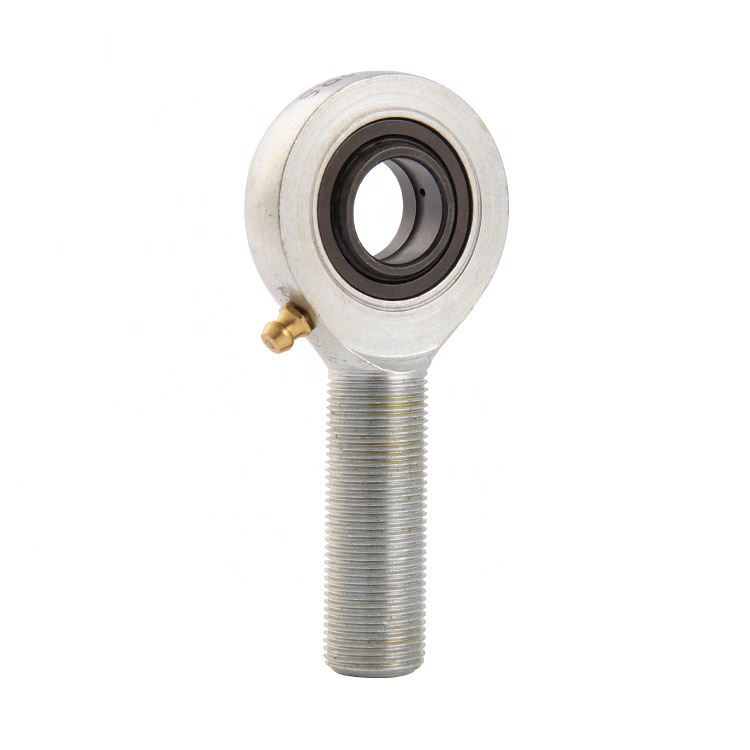
[0001] The present invention relates to a bearing, and more particularly, to an injection-molded screw hole-connected rod bearing.
【Background technique】
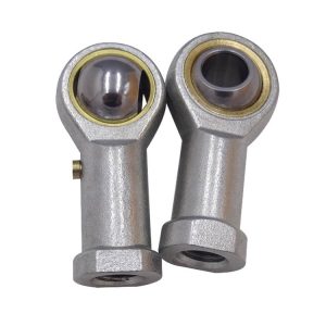
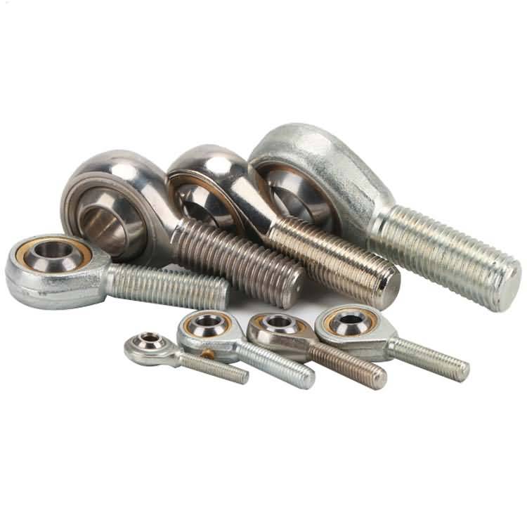
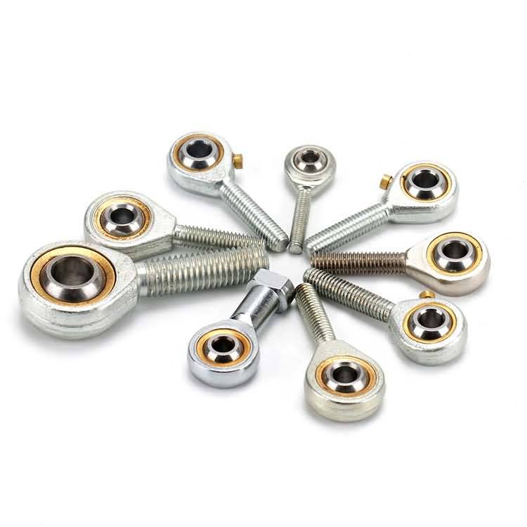
[0002] The rod bearing includes a bearing body, one end of the bearing body is provided with a threaded hole, the other end is provided with a shell, a steel ball is worn in the shell, and a brass inner liner is provided between the shell and the steel ball. The inner hole of the shell is cylindrical. After the brass inner liner is pressed into the shell, both edges of the inner hole of the shell need to be riveted in the middle direction so as to achieve the purpose of fixing the brass inner liner, but the shell and the brass inner liner There is a gap between them, which makes the rod end bearing weak in impact resistance and not wearable, and it is prone to loosening or even disintegration during use. In order to solve the above problems, an injection-type screw hole-connected rod end joint bearing was designed. In China Patent No. 2009201478462, the authorized publication No. cn201407281U, and the patent document titled “injection type rod end joint bearing” discloses an injection-type screw hole-connected rod end joint bearing. Injection-molded rod bearing are to replace the brass collar with a composite material and injection molded between the shell and the ball. Although injection-molded rod-end joint bearings have better wear resistance than brass bushings, they can be rotated without adding lubricating oil, but wear resistance is still not as good as adding lubricating oil.
【Utility Model Contents】
[0003] The utility model provides an injection-type screw-hole-connected rod-end ball joint bearing capable of carrying out lubrication and adjustable filling nozzle direction, which solves the problem that the existing injection-molded rod-end joint bearing can not be lubricated and lubricated problem.
[0004] The above technical problems are solved by the following technical solutions: An injection-type screw hole-connected rod bearing includes a bearing body, and one end of the bearing body is provided with a threaded hole, and the other end is provided with a housing. A steel ball is put into the shell, and an injection groove is arranged on the inner wall of the shell. A liner ring is injected in the injection groove, and the steel ball is supported by the shell through the collar and the steel.
The ball is provided with a shaft hole, which is characterized in that it also includes a connection mechanism, the housing is provided with a filling hole penetrating to the steel ball, the filling hole is spherically fitted with a filling nozzle, and the filling nozzle passes through the connection. The mechanism is fixedly connected with the housing, and the connection mechanism includes a pressing block and a bolt that drives the pressing block to press onto the surface of the filling nozzle that matches with the housing, and the bolt is screwed together with the housing. The process of refueling the utility model is as follows: rotating the bolt to make the pressing block release the pressing and fixing action on the refueling nozzle, and then rotating the refueling nozzle to the inlet end of the refueling nozzle according to requirements can be conveniently connected with the refueling gun, and then To turn the bolt, the bolt drives the pressure block and presses on the nozzle, so that the nozzle and the housing are fixed. Finally, the nozzle is docked with the nozzle to add the lubricant to the ball and the injection ring. between. The convenience of refueling is good.
[0005] The utility model further includes a support ring for supporting the fuel filler nozzle in the oil filling hole, and the fuel filler nozzle and the oil filler hole are in clearance fit. Can make it easier to turn the refueling nozzle.
[0006] Preferably, the support ring is fixed to the oil filling hole. The support ring can reliably connect the nozzle and the housing together regardless of the angle of rotation of the nozzle.
[0007] Preferably, the refueling nozzle is provided with a spherical head, the refueling hole is provided with a spherical cavity, and the refueling mouth is hinged together with the refueling hole by the spherical head being locked in the spherical cavity. Compact structure, reliable connection.
[0008] Preferably, the center line of the bolt passes through the center of the fitting surface of the filler mouth and the filler hole. It can further reduce the damage to the surface of the filler mouth when the pressure pieceis pressed against the surface of the filler mouth.
[0009] Preferably, there is a spherical fit between the pressure block and the fuel nozzle. The compaction block has less damage to the surface of the injection liner and can extend the service life.
[0010] The utility model has the following advantages: being capable of refueling, improving the wear resistance of the bearing; the direction of the refueling nozzle is adjustable, the convenience of refueling is good, and the oil gun does not interfere with the peripheral components when refueling is not possible; The phenomenon of refueling.
[drawing description]
[0011] FIG. 1 is a schematic structural view of the utility model.
[0012] FIG. 2 is a partially enlarged schematic view of FIG. 1 at A. FIG.
[0013] In the drawing: steel ball 1, shaft hole 11, collar 2, connecting mechanism 3, pressing block 31, bolt 32, bearing body 4, threaded hole 41, injection tank 5, housing 6, oil filling hole 61, The spherical cavity 62, the refueling nozzle 7, the spherical head 71, the free end 72 of the spherical head, and the support ring 73.
【detailed description】
The present invention will be further described below with reference to the accompanying drawings and embodiments.
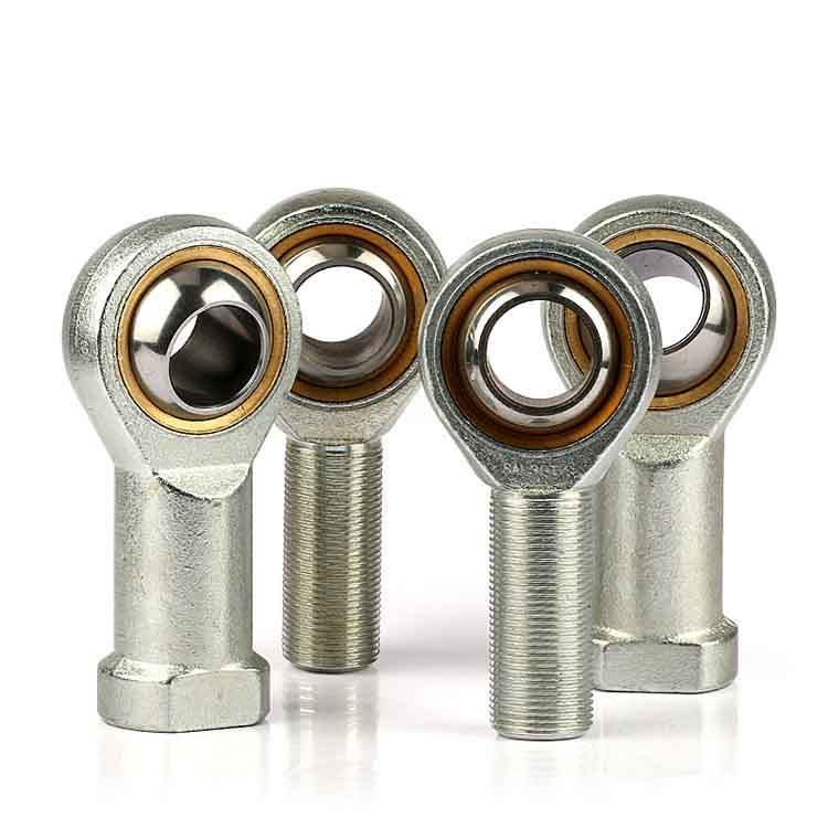
[0014] Referring to FIG. 1, an injection-molded screw hole-connected rod end joint bearing includes a bearing body 4 and a connection mechanism 3. One end of the rod bearing body 4 is provided with a screw hole 41, and the other end is provided with a housing 6. A steel ball 1 is placed in the housing 6 . The inner wall of the housing 6 is provided with an injection slot 5 . The liner ring 2 is injection molded in the injection tank 5 . The steel ball 1 is supported by the collar 2 and in the housing 6 . The steel ball 1 is provided with a shaft hole 11 . The housing 6 is provided with a filler hole 61 . The filler hole 61 penetrates the steel ball 1 and the collar 2 . The filler hole 61 is connected to the filler nozzle 7 . The refueling nozzle 7 is fixedly connected to the housing 6 through the connecting mechanism 3 .
Referring to FIG. 2, the lower end of the refueling nozzle 7 is provided with a spherical head 71. A spherical cavity 62 is provided on the inner wall of the housing 6 . The refueling nozzle 7 is snapped into the spherical cavity 62 through the spherical head 71 and hingely connected with the housing 6 , that is, the refueling nozzle 7 is hinged with the housing 6 as a spherical surface. There is a clearance fit between the spherical head 71 and the spherical cavity 62 . The spherical head 71 and the spherical cavity 62 are connected together by a support ring 73. The support ring 73 is fixed to the housing 6 . The free ends 72 of the spherical heads are all housed within the sphericalcavity 62 (ie, within the range where the filling nozzle can rotate, the free ends 72 of the spherical heads are locatedwithin the spherical cavity 62).
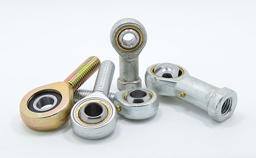
The connection mechanism 3 includes a pressing block 31 and bolts 32. The compression block 31 is housed in the wall of the spherical cavity 62 . The pressure block 31 is pressed against the surface of the filler head on the surface of the spherical head 71 that matches the housing. The compression block 31 is spherically mated with the spherical head 71 . The bolt 32 is screwed together with the housing 6 . The threaded end of the bolt 32 abuts against the pressure block 31. The center line of the bolt 32 passes through the center of the fitting surface of the filling nozzle and the housing, that is, the spherical center of the spherical surface where the surface of the spherical head 71 is located.
[0015] When it is required to adjust the direction of the fuel nozzle to be conveniently connected with the oil gun, the connection mechanism 3 is loosened to a position where the fuel nozzle 7 can rotate freely, the fuel nozzle 7 is rotated to a desired position, and then the connection mechanism is passed. 3 The fuel nozzle 7 and the housing 6 can belocked together.
[0016] The loosening and locking process of the connection mechanism 3 is as follows: the bolt 31 is rotated to drive the compression block 32 to move.
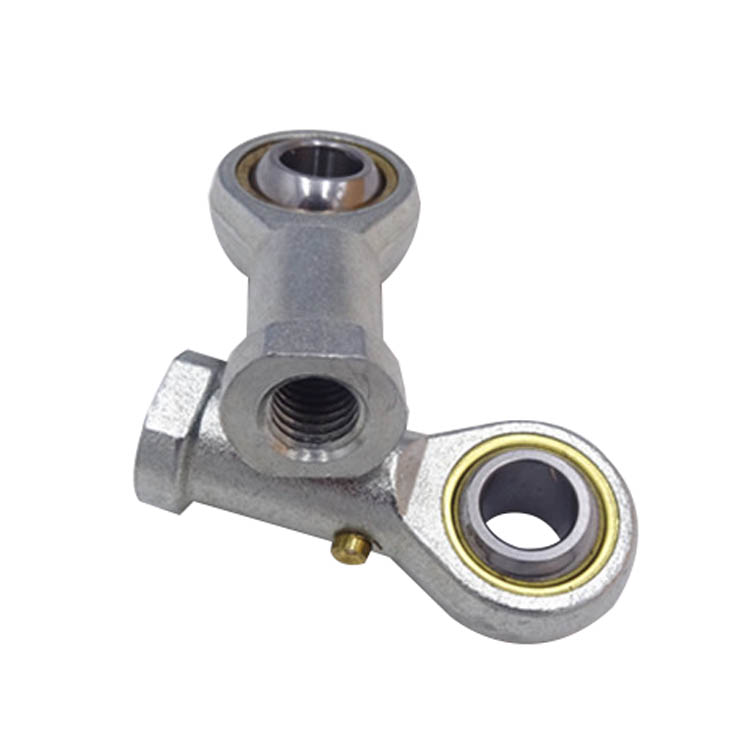
An injection-type screw-hole-connected rod bearing, comprising a bearing body, one end of which is provided with a threaded hole, the other end is provided with a shell, and the shell is provided with a steel ball,the shell The inner wall of the body is provided with an injection slot, a liner ring is injected in the injection slot,the steel ball is supported inside the casing through the liner ring, and the steel ball is provided with a shaft hole, characterized in that it also includes: a connecting mechanism, wherein the shell is provided with an oiling hole penetrating to the steel ball, the oiling hole is hingedly connected with a filling nozzle, and the filling nozzle is fixedly connected with the shell through the connecting mechanism. The connecting mechanism includes a pressing block and a bolt that drives the pressing block to press onto the mating surface of the filling nozzle. The bolt is screwed together with the housing. 2. The injection-type screw-on rod bearing according to claim 1, further comprising a support ring for supporting the fuel filler nozzle in the oil filler hole, and between the filler nozzle and the filler hole. For clearance fit. The injection-type screw hole-connected rod end joint bearing according to claim 2, wherein the support ring is fixedly connected to the oil filler hole. 4. 4. Thein jection-molded screw-hole-connected rod end articular bearing according to claim 1, wherein the refueling nozzle is provided with a spherical head, the refueling hole is provided with a spherical cavity, and the refueling mouth is The spherical head is hinged with the oil filler hole by being snapped in the spherical cavity. Theinjection-type screw hole-connected rod end joint bearing according to claim 4, wherein the center line of thebolt passes through the center of the fitting surface of the filler mouth and the filler hole. The injection-molded screw hole-connected rod end articular bearing according to claim 1, 2 or 3, wherein the pressure block and the fuel filler mouth are spherically fitted.
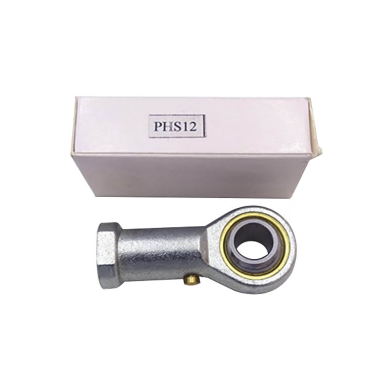
[Patent summary] The utility model relates to a rod bearing. An injection-type screw-hole-connected rod-end joint bearing includes a bearing body and a connection mechanism. One end of the bearing body is provided with a screw hole, the other end is provided with a shell, a steel ball is arranged in the shell, and an inner wall of the shell is provided. Injection tank, injection molding tank with a liner ring, steel ball through the liner ring support and the shell, the ball is equipped with a shaft hole, the shell is provided with a through hole to the steel ball, the filler hole spherical joint with a fuel nozzle, refueling The mouth is fixedly connected with the shell through the connecting mechanism, and the connecting mechanism includes a pressing block and a bolt that drives the pressing block to press the surface of the filling nozzle that matches with the shell, and the bolt is screwed together with the shell. The utility model provides an injection-type screw hole-connected rod bearing-end joint spherical bearing capable of carrying out oil lubrication and adjustable direction of a filling nozzle, and solves the problem that the existing injection-molded rod bearing end joint bearing can not be lubricated by lubrication lubrication.
Double row angular contact ball bearing installation is more complex than deep groove ball bearin...
Failure reason of micro miniature bearing About 40% of the failure of micro miniature bearings i...
Novice Mistakes 1: Do not consider the characteristics of your own actions, blindly choose Althou...
When assembling cnc machine bearings, the Venus machine tool must be preloaded, so that the origi...
Performance characteristics of stainless steel self-aligning ball bearing Self-aligning ball bear...
The long board has a strong sense of operation and is quick to get started. The longboard is a mu...
The tapered thrust bearing with cage is a split design so that the two washers as well as the rol...
Disassembly of the tapered needle bearing: When the bearing is to be used continuously after it i...

TEL: +86 183-6303-1398
E-mail: [email protected]
E-mail: [email protected]
Whatsapp: +8618668909563
Whatsapp: +8618363031398
ADD: Room E3-1203, Mingquanchunxiao, Dikou Road, Tianqiao District, Jinan City Shandong Province, China.